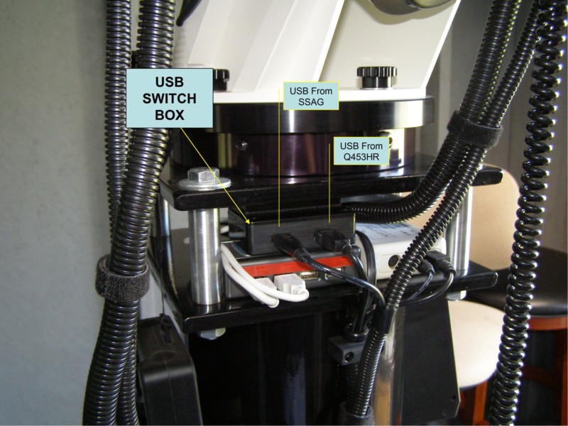
USB SWITCH BOX- Remotely Controlled This gives me the ability to connect and/ or re-connect cameras remotely. Particularly, when they crash and the only way is to physically unplug and re-plug the USB connections. I have two cameras in the switching circuit. The Main: Q453HR + The Guider: Orion SSAG Both plug into the USB SWITCH BOX and the outputs then plug into the USB HUB at the pier. |
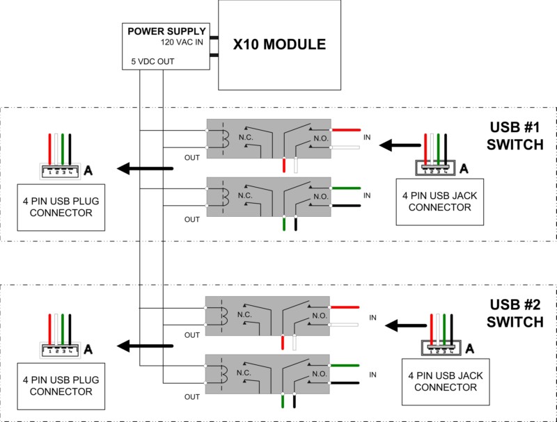
THE WIRING DIAGRAM USB Cable uses 4 wires: Red (5vdc) White (Data -) Green (Data +) Black (Ground) All connections were straight-though, one to one, using the N.O. relay contacts only. NOTE: the Cable Shield wire is not shown in this diagram, but must be connected to the metal post of each USB Surface Mount Connector. Used (4 each) DPDT miniature 5vdc DIP relays. Could not locate small 4 pole relays, so (2) relays were used per each USB connection. A wireless X-10 APPLIANCE MODULE controls power to the AC/5vdc supply for activating the relays. |
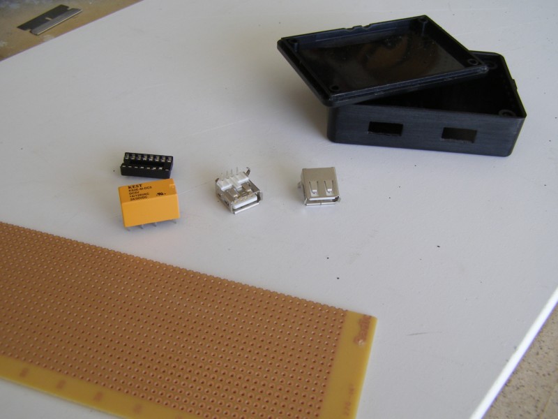
PARTS USED 1- Small plastic project box 1- Radio Shack printed circuit board/ dot copper trace 2- USB-A JACK connectors PC surface mount 4- 16 pin IC sockets 4- 5 VDC DPDT DIP relays 1- USB-A cable/ plug connectors on both ends (not shown) 1- Power Jack and Plug set (5.5mm OD x 2.1mm ID) (not shown) |
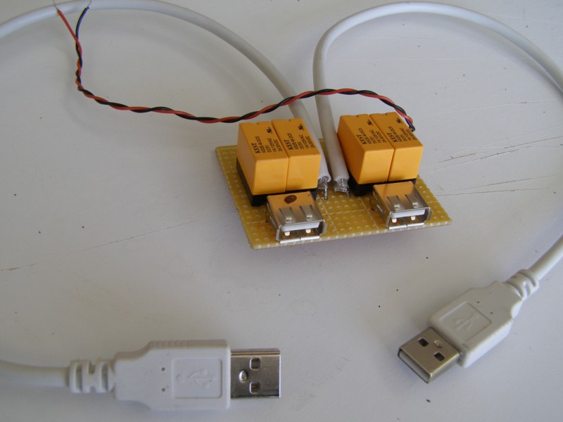
ALL COMPONENTS MOUNTED ON BOARD Everything is mounted close as possible..........I wanted the USB wiring to be very short. The twisted red and black is the 5vdc to power the relays. |
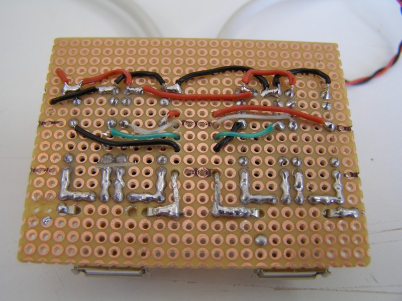
BACK-SIDE WIRING The soldering was very tedious. I used the extra wire from the USB cable to wire the board, since it was small and flexible enough. Some of the wiring connections could be made directly on the board, by "bridge soldering" between dot connectors..........................very, very carefully!! Needless to say, I used a visor-magnifier and pencil soldering iron to do this project. ALSO NOTE: Not shown in the wiring diagram................the USB cable braided shield wire must connect to each of the USB surface mounted posts. Shown just below the call-out "Shielding Connection". |
Shielding Connections |
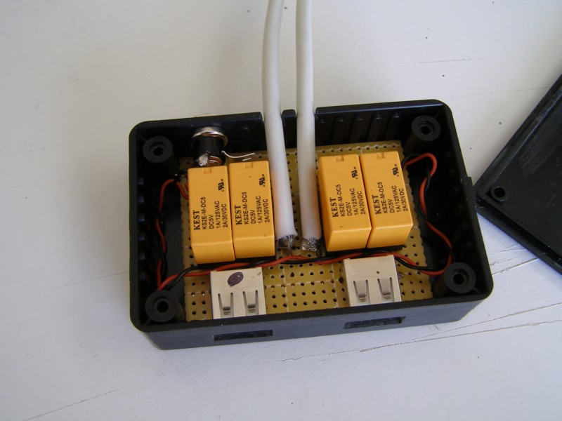
MOUNTED IN BOX The board was cut to fit snugly into the plastic box. Power connector (5.5mm OD X 2.1mm ID) shown mounted at back of box for the 5.2vdc control signal) |
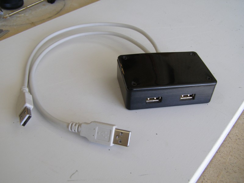
FINISHED- Front View |
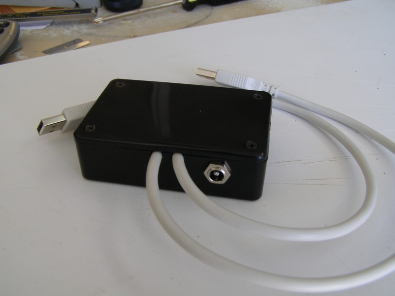
FINISHED- Back View showing 5 vdc power plug. |
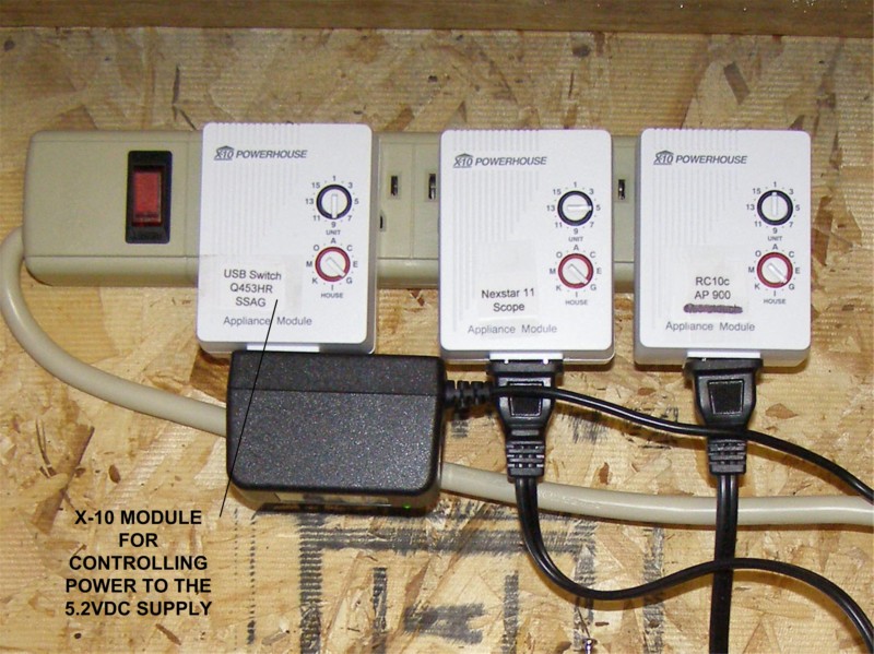
X-10 MODULES Some of the modules shown for various controls.........ie; USB Camera Switch. |
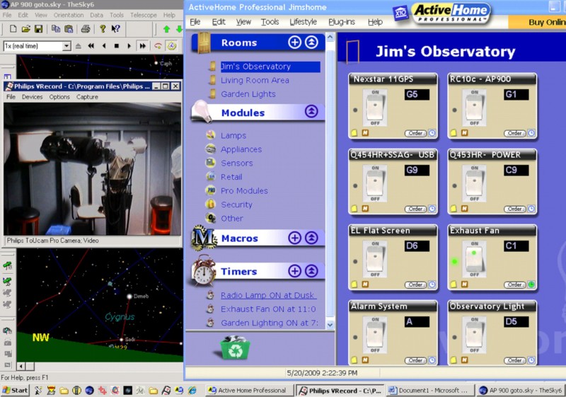
X-10 SOFTWARE CONTROL SCREEN Most functions of the observatory can now be controlled with the X10 system. With Desktop Remote everything can be controlled/ monitored from inside the home office computer. |